Modifications
Backup battery mod (no more coin cell battery)
That latest versions of the boards do not have the coin cell battery anymore. The backup power comes from the main battery. This had pro's and con's. The pro is that you do not need to worry about changing the battery every 3 years, however when the main battery gets drained below the shutoff point the clocksettings are lost.
Alle we do is simply stealing a little energy from the main battery and since that can have a higher voltage than the backup circuit can handle we need to lower the voltage, this is done with 3 1n4148 or similar small signal diodes in series, as precaution we solder a 1k resistor on the battery+ line so if anything goes wrong no high currents can flow. Please remove the coin cell holder or make sure I can not short out the circuit when the contacts can touch.

Adding a wriststrap
David Galens did organize a nice workshop for building TeensyBat detectors, he told me he had a wish for a wrist strap. He, like my self already dropped the detector several times and nothing bad happened but it is better to be safe than sorry.
I tried to make a simple loop from 1mm UHMWPE cord, tied tied that into a loop an pulled the loop through a 2mm hole in the enclosure so that the knot on the inside keeps the loop in place, To pul the loop through, I tied a thin thread to the loop, and pulled that thread through using a small electronic component with a small hook bent on the end of it. This makes an easy attachable loop for a wrist strap.

USB data on USB-C connector
In software version v1.6 we have MTP that allows us to read the micro-SD card thru the micro-usb port.
If you want to use the USB-C in stead of the micro-USB connector it is possible to connect the two small pads near the USB connectors. On the Teensy PCB and Mainboard you will find similar tiny pads.
Simply connect as in the pictures. Connect the USB-C to a USB-A port on your computer and switch on the detector, this should work just as well as connecting the micro-USB to ans USB port on your computer (only difference is you do not need to switch on power when you use the micro-USB) Pads on the mainboard are TP1 and TP2 on the Teensy there is no designator.


Adding battery monitor to V0.7 PCB (only applies to this version)
Although it was never advertised, the V0.7 PCB was intended to be equipped with a battery monitoring chip.
The chip did actually make it to the PCB but I managed to make several mistakes of which I thought they could not be fixed.
(Later board versions have this problem fixed and the battery monitor works without extra modifications)
As it seems it is possible to get it working, you need a 150ohm resistor and 10nF capacitor and two pieces of thin wire.
Separate the I2C pins from pins "3" and "4" and connect the to pins "24" and "25" (check datasheet for pin numbering or simply look at the photo below)
Now connect a 150 ohm resistor to the 3v3 pin for the Teensy, the other end goes to pin3 of the MAX17043.
The 10nF capacitor is between pin 3 and GND, in the picture I soldered it to C18 GND pad.
It is important to check for shorts to GND or "Cell". Measure ohms between Pin3(resistor) and both ends of C30.It should be at least several kilo ohms.
This only works with software later than V1.31!

Internal speaker.
Yes, I know there is hardly any space, and I like to use headphone anyway. Using headphones reduce feedback issues, low frequency time expanded or heterodyne sounds in the recording and nosy passers-by.
But every once in a while you have the urge to let people listen and have no externa amplified speaker with you. Well it turns out there is a tiny speaker that fits between the display and controls. A tiny low voltage amplifier can make just enough sound and adding a power switch allows you to turn it off.
This is the idea.

I know it is hard to find the space but this is how I managed to build it into one of my detectors. Flimsy wires pass from one side of the board to the other via holes for an optional capacitor. Next to the GPS power switch I drilled holes for an additional switch. (insulate switch pins by drilling away the GND plane around them) (Do not forget to cut a hold in the enclosure)

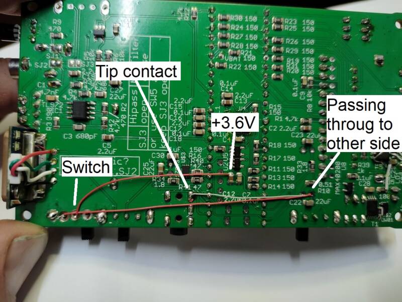
Here we see the amplifier PCB, connected with ground to the metal shield. If you do not have a GPS receiver you do not need a shield. Simply find some other GND connection, or scrape some green coating off the main board where you have a GND plane.
Pins from left to right is switched 3.6V, than input signal, GND, mute(left open) Speaker + and -.

The volume of this speaker is quite low so you have to turn up the volume, a high volume however can give feedback issues, so an internal speaker can be nice but keep in mind you can also create problems.
Modifications for teensy 3.6 based version (v0.2 PCB)
As with every design, there is always room for improvement and requests. I liked to have GPS data stored in the wav file and this calls for a GPS receiver.
In the first boards that were sold there was no space reserved for a GPS receiver, but you can cut-out a small piece of the PCB in te top right corner to make some space for a GPS receiver. A small 18x18mm GPS like the Beitian BN180 or a Ublox of this size works well enough. It has to be small unit with integrated antenna. Others pick up too much noise, You also need to apply some shielding to the Teensy. We do use biderectional communication now, this is not in the schematic, but pin RX of the GPS unit should connect to TX(pin 1) of the Teensy.
Another addition to the data gathering is a temperature sensor. The code supports a dallas temperature sensor.
Maybe the most useful one is the backlight mod. The blacklight modification allows the brightness to be controlled by the Teensy. This works very nice on autorecord mode, this display can be switched off during autorecord to save battery power. For the backlight modification to work properly, you need to have the later version TFT display, the one with Q1 on the display PCB.
The schematic with all these 3 modifications looks like this.

Backlight control modification

